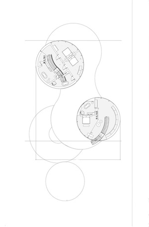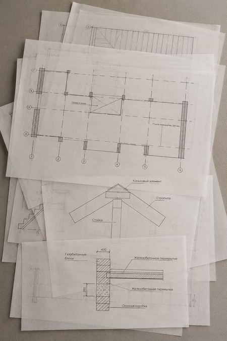
As part of the project, a set of architectural and construction drawings was developed, which includes foundation plans, slab and truss system plans, structural sections, and element connection details. The drawings were executed in AutoCAD, specifying main dimensions, construction materials, and the features of the structural solutions.
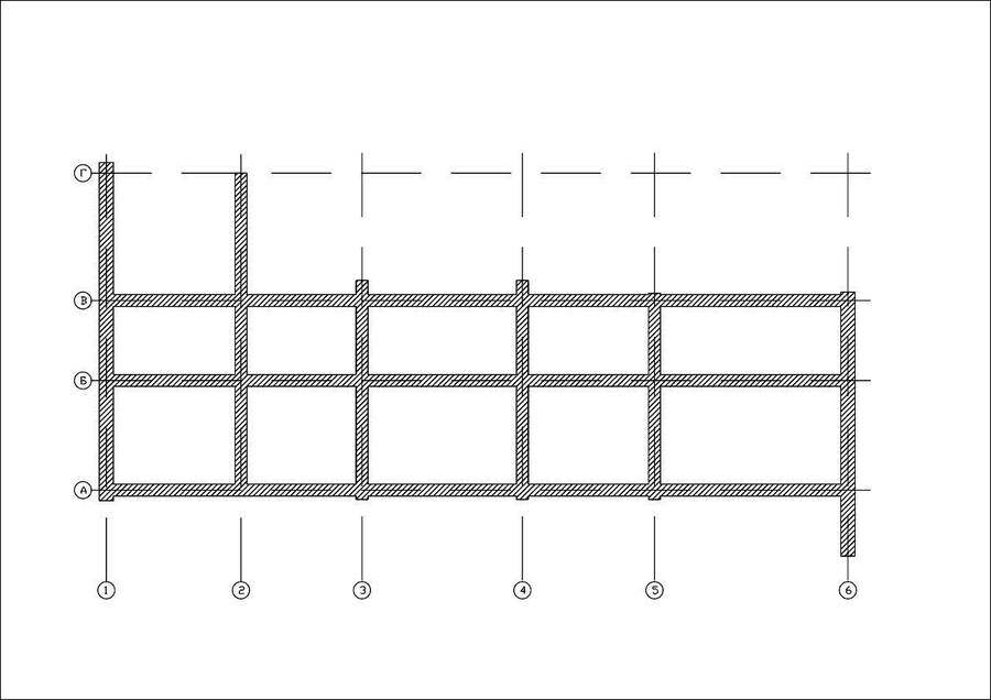
Foundation plan at cut-off elevation. 1:100 scale.
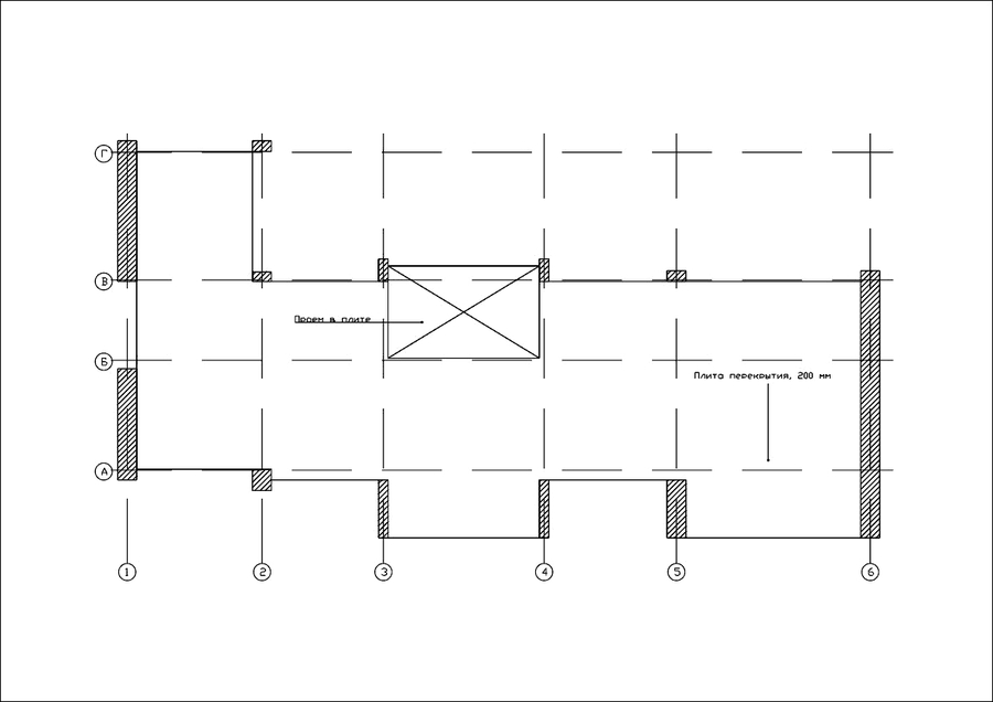
Cover plan at 2nd-floor elevation. M1:100
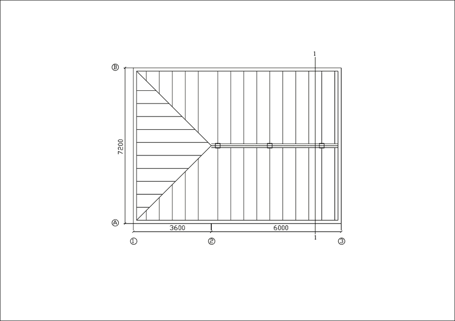
Roof truss system plan. 1:100
Attic section. Scale 1:100
«Truss» node. M1:20
Cross-section of the exterior wall. M1:20
Cross-section through the interior wall. M1:20
Window lintel installation node. M1:20
Window lintel cross-section. 1:20
Upper landing of the staircase. M1:20
Partition connection point to the ceiling. M1:20
Partition anchoring point to the floor. M1:20
Partition mounting point to structural wall. M1:20